Wednesday, March 30, 2011

Accelerometer calibration code

This is the microcontroller code that I used to calibrate the SCA3000 accelerometer as described in the previous post. This will send the measurements through the serial port at a baud rate of 9600.

/* Calibration routine for the SCA3000 accelerometer
 * using the WaveShare STK128+ Standard development
 * board with voltage level jumper set to 3.3 V

 * SCA3000 MOSI -> PB2(MOSI)
 * SCA3000 MISO -> PB3(MISO)
 * SCA3000 SCK -> PB1(SCK)
 * SCA3000 CSB -> PB4
 * SCA3000 RST -> PB5
 * SCA3000 INT (not connected)
 * SCA3000 VIN -> 5 V from USB port
 * SCA3000 GND -> common ground

 * CP2102 USB Converter RX -> PD3 (TXD1)
 * Onboard LED -> PB0
 */


#include <avr/io.h>
#include <stdio.h>
#include <util/delay.h>
#include <string.h>


// _delay_loop_2(18432) = 0.01 s

// Accelerometer readings (x, y, z)
int16_t readings[3];


void SPI_MasterInit(void)
{
   uint8_t i;

   for(i = 0; i < 100; i++)  // 1 sec delay
      _delay_loop_2(18432);

   // Enable pull-up on PB4(CS0)
   PORTB = _BV(PB4);
  

   // Set PB0(LED), PB1(SCK), PB2(MOSI) and PB5(RST0) as output low
   // Set PB4(CS0) as  output high
   DDRB = _BV(DDB0) | _BV(DDB1) | _BV(DDB2) | _BV(DDB4) | _BV(DDB5);

   // Enable SPI, Master, set clock rate fck/16
   SPCR = _BV(SPE) | _BV(MSTR) | _BV(SPR0); // 460.8 kHz

   for(i = 0; i < 100; i++)  // 1 sec delay
      _delay_loop_2(18432);

   // Release SCA3000 reset (PB5)
   PORTB |= _BV(PB5);

   for(i = 0; i < 25; i++)  // 0.25 sec delay
      _delay_loop_2(18432);
}


// Read accelerometer x, y and z axis
void readAccelerometer(int16_t* reads)
{
   uint8_t azh, azl, ayh, ayl, axh, axl;

   // Select SCA3000
   PORTB &= ~(_BV(PB4));

  
   SPDR = 0x09 << 2;
   while(!(SPSR & _BV(SPIF)));

   SPDR = 0x00;
   while(!(SPSR & _BV(SPIF)));
   azh = SPDR;
   SPDR = 0x00;
   while(!(SPSR & _BV(SPIF)));
   azl = SPDR;
   SPDR = 0x00;
   while(!(SPSR & _BV(SPIF)));
   ayh = SPDR;
   SPDR = 0x00;
   while(!(SPSR & _BV(SPIF)));
   ayl = SPDR;
   SPDR = 0x00;
   while(!(SPSR & _BV(SPIF)));
   axh = SPDR;
   SPDR = 0x00;
   while(!(SPSR & _BV(SPIF)));
   axl = SPDR;


   // Deselect SCA3000
   PORTB |= _BV(PB4);


   reads[2] = ((((int16_t)azh) << 8) + azl) >> 3;
   reads[1] = ((((int16_t)ayh) << 8) + ayl) >> 3;
   reads[0] = ((((int16_t)axh) << 8) + axl) >> 3;
}


// Take 64 readings and calculate the average
void readAverage(void)
{
   int32_t x_accu = 0;
   int32_t y_accu = 0;
   int32_t z_accu = 0;
    
   for (uint8_t i = 0; i < 64; i++)
   {
       readAccelerometer(readings);

       x_accu += readings[0];
       y_accu += readings[1];
       z_accu += readings[2];

       _delay_loop_2(7089);    // 1/260 s delay
   }

   
readings[0] = x_accu / 64;
   readings[1] = y_accu / 64;
   readings[2] = z_accu / 64;
}


static int uart_putchar1(char c)
{
   loop_until_bit_is_set(UCSR1A, UDRE1);
   UDR1 = c;
   return 0;
}


int main(void)
{
   uint8_t i;

   char buffer[64];

   for(i = 0; i < 100; i++)  // 1 second delay
      _delay_loop_2(18432);

   /* enable serial port UART1 */ 
   /* Set baud rate : 9600 bps @ 7.3728 MHz */
   UBRR1L = (unsigned char)(47);
   /* Enable transmitter */
   UCSR1B = _BV(TXEN1);

   SPI_MasterInit();

   
   while(1)
   {
      PORTB ^= 0x01;  // toggle LED

      readAverage();

      sprintf(buffer, "%5i %5i %5i", readings[0], readings[1], readings[2]);

      for(i = 0; i < strlen(buffer); i++)
         uart_putchar1((unsigned char)(buffer[i]));

      uart_putchar1('\r');
      uart_putchar1('\n');
   }
}


UPDATE :
I am now using an improved procedure for accelerometer calibration, which adds a correction for axis misalignments (cross-talk).
See:


Monday, March 28, 2011

Heel and pitch angle from accelerometer

In the development of my custom tilt-compensated compass, I have chosen to use the SCA3000 3-axis accelerometer.

One important benefit of having an accelerometer is that it can also provide the boat’s heel and pitch angles. But first, the accelerometer has to be properly calibrated.

The Freescale AN3447 Application Note (“Implementing Auto-Zero Calibration Technique for Accelerometers”) describes 4 different techniques to calibrate an accelerometer. In order of decreasing accuracy, they are:

1. Manual 0g X, Y, Z Full Range Calibration
2. Simple 0g X, Y, Z calibration
3. Freefall Calibration
4. Simple 0g X, 0g Y, +1g Z calibration

The last one (no. 4), although not the most accurate, is the more convenient to use and provides good performance in many applications. A complete implementation can be found here: http://mbed.org/cookbook/IMU.

But for my project, I definitively want to go with the most accurate technique (no. 1) in order to meet the design goals.

Here is a description of the setup used for the calibration.


I am using a development board with the new ATmega128A chip.


The ATmega128A chip can be operated at any voltage between 2.7 and 5.5 V, replacing both the ATmega128 (5V) and ATmega128L (3.3V). I am using the board at 3.3 V, with the onboard crystal of 7.3728 MHz. (There is room on the board for installing a 16 MHz crystal for 5V operation). The development board is powered from the USB port of a laptop.

The Sparkfun SCA3000 breakout board is connected trough the SPI bus plus a reset line. The breakout board is also powered from the USB port, as it has its own 3.3V voltage regulator that cannot be bypassed.

A calibration routine has been programmed in the ATmega128A that continually reads the accelerometer outputs, and after each bunch of 64 readings, send the average of each axis on the serial port with Hyperterminal showing the results on a laptop.

The calibration technique requires that you record the maximum and minimum values independantly for the 3 axis. The reason that we take an average over 64 values instead of an instantaneous value is to cancel the noise that would otherwise lead to overestimate the sensitivity. The AN3447 Application Note describes the process as tedious, and yes it is. You have to be patient and explore all the minute positions around the min and max values of each axis, while taking care of recording output values only when the accelerometer is completely at rest.

This is what I get after calibrating:


The sensitivity is calculated as (max- min)/2 and the 0-g bias as (max – sensitivity). In the datasheet of the SCA3000, the nominal sensitivity is reported as 1333 counts /g. From now on, the g-value for each axis will be calculated as:

               Ax (or Ay or Az) = (measurement – bias) / sensitivity.

Theoretically, we should find that SQRT(Ax2 + Ay2 + Az2  ) = 1. In practice, there will be a small difference that we can eliminate by normalizing the results. But it is not required if all we want is to calculate the heel and pitch angles, as the results will be the same with or without normalization.
The Freescale AN3461 Application Note (“Tilt Sensing Using Linear Accelerometers”) explains how you can get the best numerical resolution from a 3-axis accelerometer by calculating the heel and pitch angles as:  

Once calibrated, this is what I observe with the breadboad sitting still on the table.  This is a measurement of the actual alignment offset of the accelerometer vs the breadboard (in fact vs the ground) :
heel = -0.52 deg, pitch = 0.57 deg.


UPDATE :
I am now using an improved procedure for accelerometer calibration, which adds a correction for axis misalignments (cross-talk).
See:


Wednesday, March 23, 2011

Measuring boat speed (Part 2)

In the previous post, I described in a general way how the boat speed is measured. I present here the part of the microcontroller code that is used for this task.

volatile uint16_t icp3_start_time;
volatile uint16_t icp3_period;
volatile uint8_t zero_flag;
double boat_speed;
uint16_t period3;
uint8_t sreg;

/*
 * This interrupt routine is called each time
 * a new pulse rising edge is detected
 */
ISR(TIMER3_CAPT_vect)
{
   uint16_t icr3;

   uint16_t test_period;

   /*
    * Make a copy of the timer value saved in the ICR3 register
    * when the rising edge of the pulse occured
    */
    icr3 = ICR3;

   if(zero_flag)  // this is the first pulse of a new series
   {

      /*
       * Save the start timestamp in a global variable
       * for further use
       */
       icp3_start_time = icr3;

      /*
       * Push the timeout window forward by moving the OCR3A timeout
       * value just behind the capture timestamp so that the timer
       * will have to go through nearly a whole cyle before reaching OCR3A
       */
       OCR3A = icr3 - 100;

      /*
       * Next time, go to the 'else' section to calculate the time
       * interval unless a timeout has occured meanwhile, setting back
       * the zero_flag to 1
       */
       zero_flag = 0;
    }
    else
    {
       /*
        * Calculate the number of timer ticks since the last pulse
        */
        test_period = icr3 - icp3_start_time; // length of previous period

       /*
        * This is a debouncing test that is probably not required, but
        * safe to keep. If icp_period is less than 200, this means that
        * the nominal boat speed will be calculated at more than 16.6 knots,
        * an indication of a false or noisy pulse that should be discarded
        */
        if(test_period > 200)   // if we have a good pulse
        {
           icp3_period = test_period;

           icp3_start_time = icr3;    // icr3 becomes the new start time
           OCR3A = icr3 - 100;     // move the timeout window
        }
    }
}
¸
/*
 * This interrupt routine is called when the timeout
 * period is reached, i.e. TCNT3 = OCR3A (boat speed less than 0.05 knot)
 */
ISR(TIMER3_COMPA_vect)
{
   // tell everyone that we have a zero speed
   zero_flag = 1;
}

void init_timer(void)
{
   // Set timer/counter 3 with a prescale of 1024
   // and with input capture on rising edge
   TCCR3B = _BV(ICES3) | _BV(CS32)| _BV(CS30);
   TCNT3 = 0;    // initialize timer/counter 3
   ETIMSK |= _BV(TICIE3);    // enable input capture interrupt

   OCR3A = 0;  // inialize timeout value
   ETIMSK |= _BV(OCIE3A); // enable output compare interrupt
}

int main(void)
{
   // ...

   zero_flag = 1;

   init_timer();

   /* enable interrupts */
   sei();

   boat_speed = 0.0;

   for(;;)
   {
     // begin a new cycle

     // ...

     // calculate the measured boat speed
     if(zero_flag)
        boat_speed = 0.0;
     else
     {
        sreg = SREG;

        cli();  // disable interrupts while we transfer a volatile 16-bit value
        period3 = icp3_period;
        SREG = sreg;  // re-enable interrupts

        boat_speed = 1.0 / (period3 * 0.000064 * 4.7);

        // get the calibration correction factor
        // ...

        // apply the calibration correction factor
        boat_speed *= calbat;
     }

     // put the result in the data structure
     dump_info.mbs1 = boat_speed;

     // ...

     // Wait for timer signal to begin a new cycle

     // ...
   }

Measuring boat speed (Part 1)

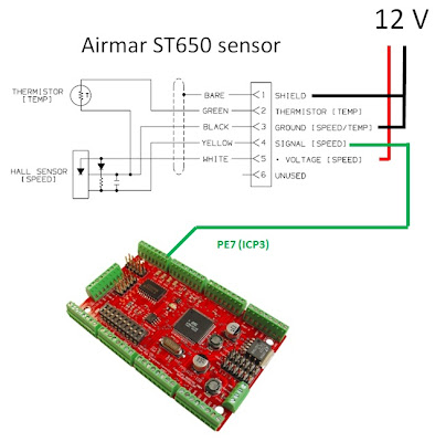
The boat speed is measured with Airmar ST650 speed sensors (similar to the newer ST850). The sensor produces two pulses per revolution of the paddlewheel. The following figure illustrates the interface between the speed sensor and the microcontroller. The ouput signal is fed directly to an input pin of the microcontroller, without further conditioning.  The pulses are detected as clean changes in logic level by the internal circuitry of the microcontroller. The thermistor is not used here.


The nominal pulse rate of the ST650 (without fins) is 4.7 Hz per knot.  Here is the form of the signal produced for a nominal speed of 3.0 knots.


Conversely, by measuring the time between the rising edges of two pulses, we can calculate the corresponding boat speed:
                                            
                              Speed (knots) = 1 / (delta_t * 4.7)

To measure the time interval, we set up a 16-bit timer running at 16 MHz / 1024 = 15625 Hz. This timer has a resolution of 1/15625 = 0.000064 second. The timer counts from 0 to 65535 then overflows to 0 and up again to 65535. Its time span is thus 65536 * 0.000064 = 4.19 seconds, which corresponds to a nominal boat speed of 1 / (4.19 * 4.7) = 0.05 knot. If the time span between 2 pulses is longer than that, we put the speed to zero. As an example, when the speed is 3.0 knots, there are 0.0709 / 0.000064 = 1108 timer ticks between each pulse. To get the boat speed, we count the timer ticks between each pulse and multiply them by 0.000064 s to get the time interval. We can then calculate the nominal boat speed, which will be multiplied later on by a calibration factor to get the final MBS (measured boat speed).

To implement this in the ATMega128, we use the input capture facility that comes with the internal 16-bit timers. When the rising edge of a new pulse is detected, the current timer value is saved in a special register, and an interrupt is fired. During the interrupt service routine, we calculate the timer counts since the last pulse and put the result in a variable that will be used by the main program to calculate the final boat speed of the current cycle. In the same interrupt routine, we also calculate what will be the timer value 4.19 seconds later. This is a timeout value that we push forward at each new pulse, and should not be attained as long as the boat speed is greater than 0.05 knot.

We set up a second interrupt that fires if the timeout value is attained. In the corresponding interrupt service routine, we set a flag to indicate to the main program that the speed is zero, and that the next pulse will be the first of new series.

All these commentaries will be helpful to follow the code snippets that I will present in Part 2 of this post.

Tuesday, March 8, 2011

Data transfer from microcontroller to notebook (Part 2)

In this Part 2, we now look at the data transfer from the notebook point of view. If we look at the microprocessor output sent to the notebook running Hyperterminal, all we see is garbage with ‘MERLIN’  strings appearing 10 times per second. Now we are free to do whatever we want with this data.
WARNING : the following will be of interest only to those using or willing to use the Microsoft Visual C++ environment to develop their own displays. This does not prevent using other environments to do the same thing. I have chosen to develop the real-time displays using the MFC classes in Microsoft Visual C++ 2005. This would also apply to Microsoft Visual C++ 2008 and 2010.
The first challenge is to recover the information coming through the USB port. The serial-to-USB converter appears to the notebook as a virtual COM port.
There are some classes that are available on the Internet to read from COM ports. They can be used with success when reading from real COM ports that were still available some years ago on any computer. But times have changed and we have now to live only with USB ports. When I switched from real COM ports to (USB) virtual ones, I discovered that these classes won’t do the job anymore, because they were designed to read the incoming characters one at a time at a regular and predictable baud rate. A USB-based virtual port will receive the characters at the specified baud rate on the average, but with short-term bursts and idle periods, and the old classes cannot follow.
Fortunately, these guys have developed a life-saver class that can deal with the situation:
http://cpp.developpez.com/faq/vc/?page=NetWork. Go to the section ‘Comment travailler avec le port série ?’ and you will find the source code for the class, then download the example : http://farscape.developpez.com/Samples/SerialDemo.zip to see how to use it.

I will not go through all the implementation here (look at the example for that), but I will concentrate on coding the particular function that gets called when something shows up at the virtual COM port. The communication object lives in a separate thread, and when one or more characters appear at the port, triggers the main application to call the ‘OnReceiveCom’ function. Note that all running averages calculations and updates also have to be done in this function, but they are not shown here.

This is a very partial extract of the final implementation, but the objective here is to document how to synchronize with the incoming data and repopulate the local data structure at the 10 Hz refresh rate, before asking the display window to redraw itself using this new data.

typedef union
{
   unsigned char dump[76];
   struct
   {
      float mwa; // measured apparent wind angle
      float awa; // awa corrected for heel
      float twa; // true wind angle
      float aws;  // apparent wind speed
      float tws; // true wind speed
      float wdir; // wind direction
      float mbs1; // measured boat speed (starboard)
      float mbs2; // measured boat speed (port)
      float stw; // boat speed through water
      float vmg; // velocity made good
      float heading; // corrected heading
      float heel; // heel angle
      float leeway; // calculated leeway angle
      float doc; // direction of current
      float soc; // speed of current
      float cog; // GPS course over ground
      float sog; // GPS speed over ground
      short long1; // GPS longitude (1st part)
      short long2; // GPS longitude (2nd part)
      short lat1;  // GPS latitude (1st part)
      short lat2;  // GPS latitude (2nd part)
   };
} dump_union;  //  float are 4 bytes, short are 2 bytes 


// partial extract of
class CMerlinDlg : public CDialog
{
    //...

 public:
    int counter;
    unsigned char merlin[6];
    dump_union dump_info;

    //...
}


BOOL CMerlinDlg::OnInitDialog()
{
   //...

   counter = -1;

   //...
}


/* Most of the time, this function will be called with
 * only one character in the receive buffer (nr = 1),
 * but occasionnaly there will be 2, 3 or more.
*/
LONG CMerlinDlg::OnReceiveCom(WPARAM ch, LPARAM port)
{
    int nr, i;
    char *szReceive;

    CCom *pCom=(CCom*)ch;
    szReceive = new char[(nr=(pCom->SizeUsedInRXBuf()))];
    pCom->ReadBuffer(szReceive,nr);

    for(i = 0; i < nr; i++)
    {
       merlin[0] = merlin[1];
       merlin[1] = merlin[2];
       merlin[2] = merlin[3];
       merlin[3] = merlin[4];
       merlin[4] = merlin[5];
       merlin[5] = (unsigned char)(szReceive[i]);

      
       if(merlin[5] == 'N')
       {
          if (merlin[0] == 'M' && merlin[1] == 'E' && merlin[2] == 'R'
              && merlin[3] == 'L' && merlin[4] == 'I')
          {
             counter = 0;
             continue;
          }
       }

      
       if(counter >= 0)
       {
          dump_info.dump[counter] = (unsigned char)(szReceive[i]);
          counter++;
   

          if(counter == 76)    // we have a complete data structure
          {
             counter = -1;

             // update all the running averages here
             // ...


             // command the display window to redraw itself using the new data
             dispwnd->InvalidateRect(NULL);
           }
        }
     }
   
     delete [] szReceive;
     return 0L;
}


Typical results can be seen on 2 short video clips in the following post:
http://sailboatinstruments.blogspot.com/2011/01/damping.html

Data transfer from microcontroller to notebook (Part 1)

This post will be of interest to programmers. I document how measured and calculated data are transferred from the microcontroller to the notebook, which is responsible to build the real-time displays.
In this Part 1, we look at the microprocessor side of the transfer.
For efficiency, all transferred data are in binary form, mostly in floating point format.
Within each cycle of 0.1 second (10 Hz), the microprocessor populates the ‘dump_info’ structure with measured and calculated values. At the end of the cycle, this data structure is copied to the ‘ubuff’ transmit buffer. The first 6 bytes of the transmit buffer, which contain the magic word ‘MERLIN’ , remain unchanged. This magic word will be used by the notebook to identify and confirm the beginning of a new data structure.

The transmit buffer is sent through USART0 of the microcontroller to the serial-to-USB converter, at a baud rate of 9600. This baud rate is the fastest that the notebook can handle at the other end among its other tasks. Higher baud rates could be handled by more powerful laptops, but the notebook has been chosen because of its longer battery life (around 9 hours). The transfer uses interrupt-based routines, because with poll-based strategy, it would not be possible to achieve the 10 Hz rate.


// Initialization

typedef union
{
     unsigned char dump[76];
     struct
     {
           double mwa;     // measured apparent wind angle
           double awa;     // awa corrected for heel
           double twa;     // true wind angle
           double aws;     // apparent wind speed
           double tws;     // true wind speed
           double wdir;    // wind direction
           double mbs1;    // measured boat speed (starboard)
           double mbs2;    // measured boat speed (port)
           double stw;     // boat speed through water
           double vmg;     // velocity made good
           double heading; // corrected heading
           double heel;    // heel angle
           double leeway;  // calculated leeway angle
           double doc;     // direction of current
           double soc;     // speed of current
           double cog;     // GPS course over ground
           double sog;     // GPS speed over ground
           int long1;      // GPS longitude (1st part)
           int long2;      // GPS longitude (2nd part)
           int lat1;       // GPS latitude (1st part)
           int lat2;       // GPS latitude (2nd part)
     };
} dump_union;  //  double are 4 bytes, int are 2 bytes 

dump_union dump_info;

static char ubuff[82];

int main(void)
{
     /* USART0 : Set baud rate : 9600 @ 16MHz */
      UBRR0L = (unsigned char)(103);
     /* Enable transmitter */
     UCSR0B =_BV(TXEN0);

     // initialize the magic word
     ubuff[0] = 'M';
     ubuff[1] = 'E';
     ubuff[2] = 'R';
     ubuff[3] = 'L';
     ubuff[4] = 'I';
     ubuff[5] = 'N';

     txindex = 0;

     /* enable interrupts */
     sei();

     for(;;)
     {   
          // begin a new cycle

          // Measure and calculate new data,
          // put results in dump_info structure
          // ...
          // dump_info.mwa = ...
          // dump_info.awa = ...
          // dump_info.twa = ...
          // ...
          // dump_info.long2 = ...
          // dump_info.lat1 = ...
          // dump_info.lat2 = ...
         
          // Populate the transmit buffer,
          // without changing the first 6 bytes
          for(i = 6; i < 82; i++)    // 76 + 6 = 82
               ubuff[i] = dump_info.dump[i-6];

          UCSR0B |= _BV(UDRIE0);  // start transmitting

          // Wait for timer signal to begin a new cycle
          //...
     }
}


// This interrupt routine will be called 82 times within
// the next 100 ms then will disable itself
ISR(USART0_UDRE_vect)
{
     if(txindex < 81)
           UDR0 = ubuff[txindex++];
     else
     {
           UDR0 = ubuff[81];
           txindex = 0;
           UCSR0B &= ~(_BV(UDRIE0));  // stop transmitting
     }
}